- 您现在的位置:买卖IC网 > Sheet目录316 > BD8119FM-ME2 (Rohm Semiconductor)IC WHITE LED DVR PWM 28-HSOP
�� �
�
�BD8119FM-M�
�5.� Selection� of� the� output� capacitor�
�Select� the� output� capacitor� Cout� based� on� the� requirement� of� the� ripple� voltage� Vpp.�
�Technical� Note�
�Vpp� =�
�Iout�
�Cout�
��
�Vout�
�Vout+V� IN�
��
�1�
�Fosc�
�+� IL_MIN� � RESR�
�Choose� Cout� that� allows� the� Vpp� to� settle� within� the� requirement.� Allow� some� margin� also,� such� as� the� tolerance� of� the�
�external� components.�
�6.� Selection� of� the� input� capacitor�
�A� capacitor� at� the� input� is� also� required� as� the� peak� current� flows� between� the� input� and� the� output� in� DC/DC� conversion.�
�We� recommend� an� input� capacitor� greater� than� 10μF� with� the� ESR� smaller� than� 100m� ?� .� The� input� capacitor� outside� of�
�our� recommendation� may� cause� large� ripple� voltage� at� the� input� and� hence� lead� to� malfunction.�
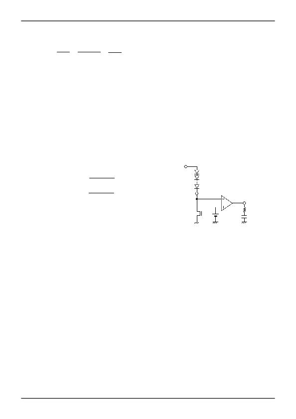
�7.� Phase� Compensation� Guidelines�
�In� general,� the� negative� feedback� loop� is� stable� when� the� following� condition� is� met:�
�?� Overall� gain� of� 1� (0dB)� with� a� phase� lag� of� less� than� 150o� (i.e.,� a� phase� margin� of� 30o� or� more)�
�However,� as� the� DC/DC� converter� constantly� samples� the� switching� frequency,� the� gain-bandwidth� (GBW)� product� of�
�the� entire� series� should� be� set� to� 1/10� the� switching� frequency� of� the� system.�
�Therefore,� the� overall� stability�
�characteristics� of� the� application� are� as� follows:�
�?� Overall� gain� of� 1� (0dB)� with� a� phase� lag� of� less� than� 150o� (i.e.,� a� phase� margin� of� 30o� or� more)�
�?� GBW� (frequency� at� gain� 0dB)� of� 1/10� the� switching� frequency�
�Thus,� to� improve� response� within� the� GBW� product� limits,� the� switching� frequency� must� be� increased.�
�The� key� for� achieving� stability� is� to� place� fz� near� to� the� GBW.�
�V� out�
�Phase-lead� fz� =�
�1�
�2� π� CpcRpc�
�[Hz]�
�Phase-lag� fp1� =�
�1�
�2� π� RLCout�
�[Hz]�
�LED�
�FB�
�A�
�COMP�
�Rpc�
�Cpc�
�Good� stability� would� be� obtained� when� the� fz� is� set� between� 1kHz� ~� 10kHz.�
�In� buck-boost� applications,� Right-Hand-Plane� (RHP)� Zero� exists.� This� Zero� has� no� gain� but� a� pole� characteristic� in�
�terms� of� phase.� As� this� Zero� would� cause� instability� when� it� is� in� the� control� loop,� so� it� is� necessary� to� bring� this� zero�
�before� the� GBW.�
�fRHP=�
�Vout+VIN/(Vout+VIN)�
�2� π� I� LOAD� L�
�[Hz]�
�I� LOAD� :� Maximum� Load� Current�
�It� is� important� to� keep� in� mind� that� these� are� very� loose� guidelines,� and� adjustments� may� have� to� be� made� to� ensure�
�stability� in� the� actual� circuitry.� It� is� also� important� to� note� that� stability� characteristics� can� change� greatly� depending� on�
�factors� such� as� substrate� layout� and� load� conditions.� Therefore,� when� designing� for� mass-production,� stability� should�
�be� thoroughly� investigated� and� confirmed� in� the� actual� physical� design.�
�www.rohm.com�
�?� 2011� ROHM� Co.,� Ltd.� All� rights� reserved.�
�13/20�
�2011.08� -� Rev.B�
�发布紧急采购,3分钟左右您将得到回复。
相关PDF资料
BD82103GWL-E2
IC LED DRVR WHITE BCKLGT 11-UCSP
BD9206EFV-E2
IC LED DRIVER 6V LCD 20HTSSOP
BD9207FPS-E2
IC LED DVR STEPDWN 1.5A TO252S-5
BH-14E_TI-20T_CTI
ADAPTER PIN CONVERTER 14-20 PIN
BH-20E_CTI-60T_TI
ADAPTER PIN CONVERTER 20-60 PIN
BH-ADP-ISO20
ISOLATION ADAPTER 20-PIN TI JTAG
BH-GANG2000
GANG2000 PROGRAMMER TI 32BIT MCU
BH-PCI-560
PCI560 JTAG EMULATOR FOR TI DSP
相关代理商/技术参数
BD813
制造商:未知厂家 制造商全称:未知厂家 功能描述:TRANSISTOR | BJT | NPN | 45V V(BR)CEO | 2A I(C) | TO-202
BD8130KN-E2
制造商:ROHM Semiconductor 功能描述:CORRECTION IC FOR TFT-LCD DISP - Tape and Reel 制造商:ROHM Semiconductor 功能描述:IC DISP CORRECTION TFT-LCD VQFN 制造商:ROHM Semiconductor 功能描述:TFT-LCD DISP CORRECTION IC
BD8132FV
制造商:ROHM 制造商全称:Rohm 功能描述:High-precision Gamma Correction ICs with built-in DAC
BD8132FV_09
制造商:ROHM 制造商全称:Rohm 功能描述:High-precision Gamma Correction ICs with built-in DAC
BD8132FV-E2
功能描述:IC PWR SUP CORRECTION SSOP-B40 RoHS:是 类别:集成电路 (IC) >> PMIC - 电源管理 - 专用 系列:* 标准包装:1 系列:- 应用:手持/移动设备 电流 - 电源:- 电源电压:3 V ~ 5.5 V 工作温度:-40°C ~ 85°C 安装类型:表面贴装 封装/外壳:14-WFDFN 裸露焊盘 供应商设备封装:14-LLP-EP(4x4) 包装:Digi-Reel® 配用:LP3905SD-30EV-ND - BOARD EVALUATION LP3905SD-30 其它名称:LP3905SD-30DKR
BD8138EFV
制造商:ROHM 制造商全称:Rohm 功能描述:y-correction IC for TFT-LCD Panel
BD8139AEFV
制造商:ROHM 制造商全称:Rohm 功能描述:High-precision Gamma Correction ICs with built-in DAC
BD8139AEFV-E2
功能描述:IC GAMMA CORRECTION 40SSOP 制造商:rohm semiconductor 系列:- 包装:剪切带(CT) 零件状态:有效 类型:TFT-LCD 稳压器 应用:视频 安装类型:表面贴装 封装/外壳:40-VSSOP(0.213",5.40mm 宽)裸焊盘 供应商器件封装:40-HTSSOP-B 标准包装:1